Engine Builder and Engine Pro present Shop Solutions in each issue of Engine Builder Magazine and at enginebuildermag.com to provide machine shop owners and engine technicians the opportunity to share their knowledge to benefit the entire industry and their own shops. Those who submit Shop Solutions that are published are awarded a prepaid $100 Visa gift card. Submit your Shop Solution at [email protected]. You must include your name, shop name, shop address and shop telephone number. Submitted Shop Solutions not published will be kept on file and reevaluated for each month’s new entries.
OIL PUMP PRESSURE TESTER
When modifying oil pumps for max relief pressure, it can be a crapshoot until the engine is running.
Pictured is one of my 50-year-old test units manufactured essentially from spare parts. A main cap, pressure gauge, and a sealable container (to eliminate contamination while being stored). Install oil, pump, prime, and drive with electric drill. This allows testing and correction prior to installation.
Archie Frangoudis Archie’s Racing Service Merrimack, NH
MORE DOWEL REMOVAL
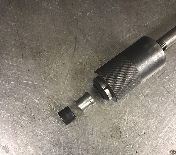
A great way of pulling precision dowels without damaging them is to make a collared spud that slip fits into the dowel. Then, use a collet-type dowel pin puller. The spud will allow the collet to clamp down without collapsing the dowel. We use this method in the locked quill of the milling machine on some rods with dowels. They generally slip out with just a little twisting and even downward pressure. This has been very helpful with doweled import main girdles and rods where the pins are hard to replace.

Ron Flood Cedar Machine North Branch, MN
PISTON TO VALVE

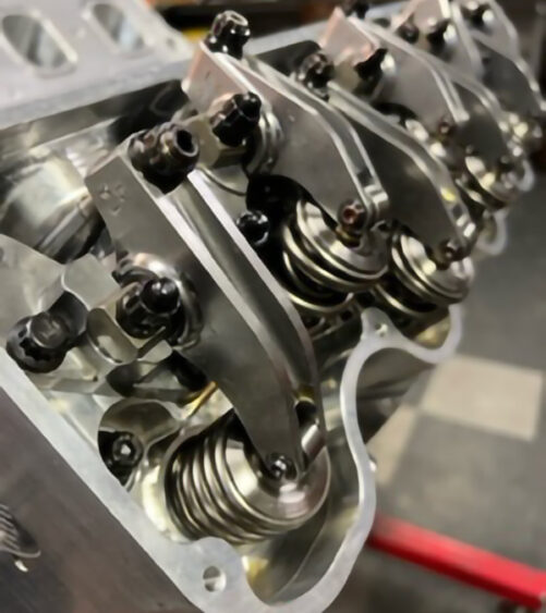
Everyone knows the clay method for piston-to-valve checks. Some people like to use a dial indicator with light “checker” valve springs installed, but that method doesn’t tell you about the actual numbers with the real valve spring installed. First, find out the tightest piston-to-valve reading for intake and exhaust with the checker springs and a degree wheel. Usually, 10 degrees BTDC and 10 ATDC. Install the actual valve springs to run, lash the valves. Setup a dial indicator on the spring retainer, and roll engine to the previously found tightest PTV location. Zero the indicator, carefully turn the Allen head lash adjuster (shaft rockers) to open the valve more and watch the indicator reading until the valve lightly stops on the piston. This number is an actual PTV reading. You will be surprised how much clearance you gain over the reading you get with light “checker” springs. Return the indicator to zero and repeat the process for both valves.
Nick Jones Automotive Machine Fraser, MI
CNC FEED AND FEED CHART

Shops with CNC mills often need to do a “quick” task, such as drilling a few holes, or taking a cut along one axis, etc. This tip discusses three methods to do so.
1. Most machines have a pendant or hand wheels, which the operator can use to move the tool in one axis. However, this manual motion is often jerky or too slow or too fast, resulting in broken tools, or a poor finish on the part.
2. Another option is using the feed-% override knob and jog buttons. Turn the feed rate % down and press the axis jog button to make a smoother, more controlled cut.
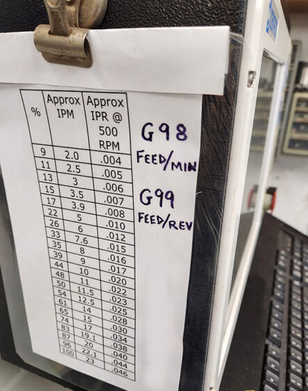
To help our employees choose where to set the feed rate %, I attached a chart (pictured) to the side of the controls. I obtained the chart’s data by simply timing several feed rate-% settings over 10” of motion.
For example, from the chart, setting the feed rate override at 22%, and pressing the X-axis jog button will move the tool along the X-axis, at 5 Inches/Minute (IPM) with the
machine in G98 mode. Note: some machines may require a separate column(s) for the Z-axis rates (drilling/boring moves).
3. An even better way to achieve single or combined axis motion for doing quick jobs is to learn a few basic G-codes, and use MDI (Manual Data Input) to type/enter simple G-code moves.
I strongly suggest operators study the machine’s manual and learn a few very basic M&G codes, such as M3, M5, M8, M9, G00, G01, G90, G91, G98, G99, S, F. Then, practice “cutting air.” Also study how tool offsets work and their related G-codes.
Here’s a simplified format to get started:
*G90 G98 G00 X0 Y0 Z15-sets ‘absolute’ position mode; sets IPM feed mode; sets full rapid feed mode; moves tool, at full rapid feed rate, to the current established X0, Y0, Z15 locations.
*M3 S500-starts the spindle turning CW at 500 rpm,
*G91 G98 G01 X2 Y-1 F12-sets the ‘incremental’ positioning mode; sets IPM feed mode; sets feed-rate mode, incrementally moves the tool along X axis +2” and along Y axis -1”, at 12 IPM.
*G90 G98 G01 Z5 F4-sets ‘absolute’ positioning mode; sets IPM feed rate mode; sets feed-rate mode, ‘absolutely’ moves tool along the Z axis to +5”, at 4 IPM.
After some experience with these simple moves, operators should begin to understand and learn additional simple M&G-code, their machine’s default and modal codes, so they can quickly and easily use MDI to do simple tasks.
Tom Nichols Automotive Machine & Supply, Inc Joshua, TX


